
TECHNICAL SPECIFICATIONS FOR SERIES RESISTANT HEATING CABLES TO BE USED IN COLD ROOM FLOOR
TECHNICAL SPECIFICATIONS FOR SERIES RESISTANT HEATING CABLES TO BE USED IN COLD ROOM FLOOR
General Features
1. Electric heating mats/cables are used for two purposes in cold rooms.
a) Preventive heating below the frost level: In order to prevent damage to the structure due to freezing of the cold room floor concrete, concrete under the ground heat insulation layer and/or water in the soil ground;
i) The heating load for this application should be at the level of 10 W/m² -15W/m².
ii) There should be a spare circuit in cold rooms below -15o C degrees.
iii) A mat prepared for this purpose should be used or if a cable is used, the cable should be laid in a strip in the form of ‘S’s not exceeding 100 cm max.
iv) The distance between the heater and the walls should be 20 cm.
v) The heating mat/cable should be under the heat insulation cover, on the water insulation layer or under the water insulation cover, in the protective concrete.
vi) The temperature sensor should be located 30-40 mm lower than the mattress/cable plane.
vii) The mattress/cable factory test report certificates must be available and recorded after ensuring that they comply with the measured values after laying.
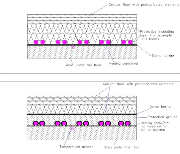
Fig. 1. Typical application with mattress
b) On both sides of the cold room entrance door, to prevent floor icing due to the temperature difference between the room and the entrance corridor when the door is opened.
i) The heating intensity for this application should be between 300 W/m² -350W/m².
ii) The area to be heated is the area as wide as the door opening and 1m deep, approximately 50-70cm of which is inside the cold room.
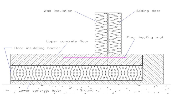
Fig. 2. Under-door heating section
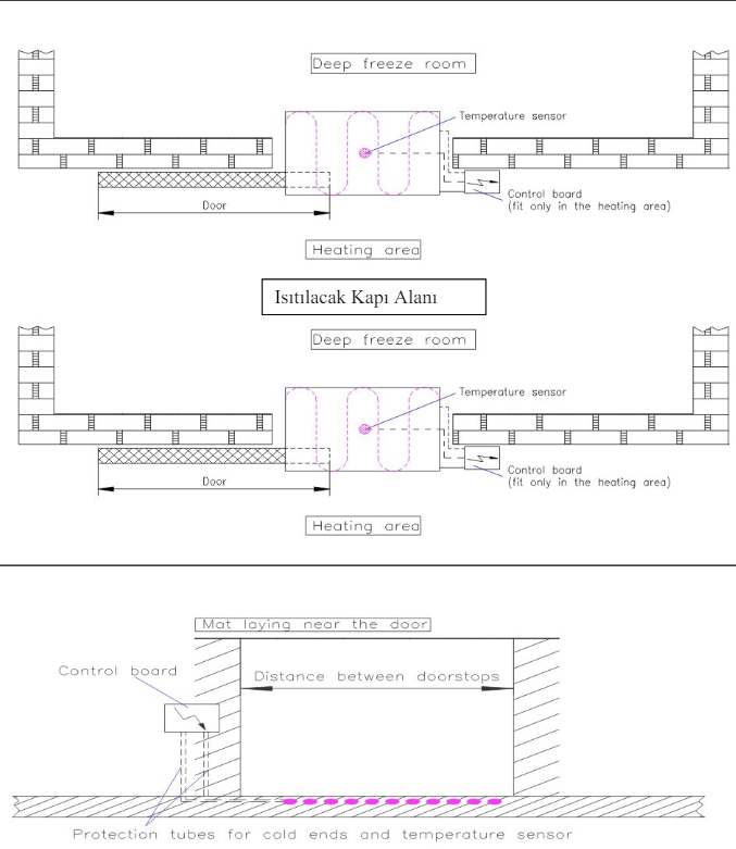
Fig. 3 and 4. Under-door heating plan and front view
2. The design and application of the heating system should be made by considering human and material safety.
3. The materials to be used in the heating system should be suitable for use under the ground, in concrete. There should be a certificate containing the manufacturing values of each heating element (mattress or cable).
4. The heating system should definitely be operated under thermostat control. The thermostat's sensitive element (sensor) should be placed at least 10-15 cm away from the heating cables in the ground and 30-40 mm lower (deeper).
5. The materials used in the heating system should be guaranteed against all kinds of manufacturing, design and application errors.
6. During the application phase, application details should be presented to the administration, and the assembly should be started after receiving approval.
7. The heating mat/cable system should be delivered to the administration in working condition after operating tests are performed at the end of the assembly.
8. At the delivery of the heating mat/cable system, all necessary technical information and maintenance, operating instructions and application projects should be delivered to the administration.
9. The application of the heating mat/cable system must be done by expert teams within the contractor company.
10. The connections of the heating mat/cable and the energy cables that feed them must be made either with additional materials suitable for remaining under the ground or in connection boxes placed in suitable places.
Connection and Joint Boxes
1. Connection boxes must have at least IP 55 protection class. Box covers must be sealed and screwed.
2. The connection of the feeding cable and the heating mat/cable must be provided through suitable terminals in the box.
3. If there is an energy cable exit from a connection box to another connection box, it is preferable to use the special terminals of the box manufacturer with suitable cross-sections in such cases. However, if rail terminals are used instead of special terminals, the upper bridges of this terminal must definitely be used.
4. All heating cable and energy cable entries and exits to the box must be glanded.
5. If the connection boxes are to be placed under the ground, precautions should be taken to ensure that the upper cover of the box can be accessed for service and maintenance purposes.
Heating Elements:
1. Heaters should primarily be preferred as ready-made mattresses manufactured for this purpose and with a spare cable. Mattresses or cables should have either a cold cable from one end where energy is supplied and a watertight termination at the other end during the production phase. In cables terminated as factory-made, there will be a cold end section suitable for phase-neutral-ground connection on the energy supply side of the heating cable. Only in cases of necessity and only after the approval of the administration, a type of cable cut at the installation site can be used.
2. The heating cable used in each heating circuit (mattress/cable) should be a single piece. Joints are unacceptable.
3. The outer diameter of the cable will not exceed 10 mm.
4. The CE certificate regarding the heating cables to be used must be present in addition to the ISO certificate of the cable manufacturer.
Thermostat and Panel
1. Heaters (mattress/cable) should be controlled and controlled with a control panel manufactured for this purpose. The panel should have an LED indicator showing that the heaters are on, alarm outputs and a test button.
2. Regardless of the power of the heating cables to be fed from the panel, the heating cables will never be fed directly from the thermostat.
3. Appropriate rated fuses should be used for the heating cable circuits to be used within the panel. There should be an independent control fuse for the power contactor coil circuits and electronic thermostat supply.
4. A leakage current switch with an appropriate rated current will be used at the panel input. The primary preference is for a leakage current switch of 30 mA. However, if the supply lines and heating cable circuit lengths are long, a 300 mA leakage current switch can be used. In applications where the 300 mA value is not sufficient, the load fed from the panel should be divided into groups and a separate leakage current switch should be used for each group.